THE PROCESS
CONNETECING MY OUTPUT DEVICES BOARD TO MY LAPTOP USING H06 BLUETOOTH MODULE
In this assignment I used my output devices board and I programed it to send and receive date from my laptop via H06 Bluetooth module. The idea is to let the board send number 0 and receive number 1 and once the board receive number 1 from my laptop it cause the led on the board to blink. Before I start working on my assignment first I started by reading the data sheet of HC-06 Bluetooth module
+ HC-06 Bluetooth datasheet HERE.
And then I decided to use Arduino Uno as an ISP programmer so after connecting Arduino board with my device I started writing and modifying the code in Arduino IDE environment so it can send number 0 via the connected Bluetooth device and receive number 1 which cause the led light to blink so for sending data from my outboard board I used the below code function
BluetoothSerial.println (0)
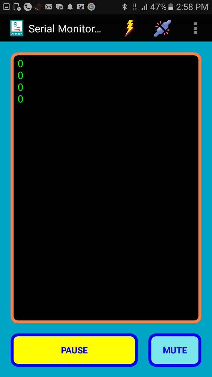
This way I was able to print number 0 in the Bluetooth serial monitor and in order to check if the sketch is working fine and to monitor the process I connected my mobile wirelessly to the Bluetooth module which was sending number 0 every few seconds as shown in image #01
The android app I used is called (TALKING SERIAL MONITOR (FREE)) and I had downloaded it free of charge via google play
Note : there are two important points I would like to mention when using the Bluetooth module
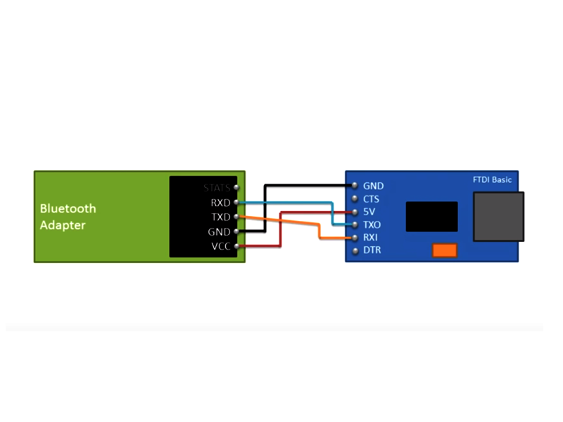
+ The 1st it is important to flip the RX & TX pins when connecting the Bluetooth device with your board.
+ The 2nd point is that the baud rate of the Bluetooth device should match code baud rate, in my case the baud rate is 9600
Briefly speaking baud rate is A number related to the speed of data transmission in a system. The rate indicates the number of electrical oscillations per second that occurs within a data transmission.
Below are at commands i used for configuring my board :
+ For Testing Connection Commands I typed AT, the answer I got OK
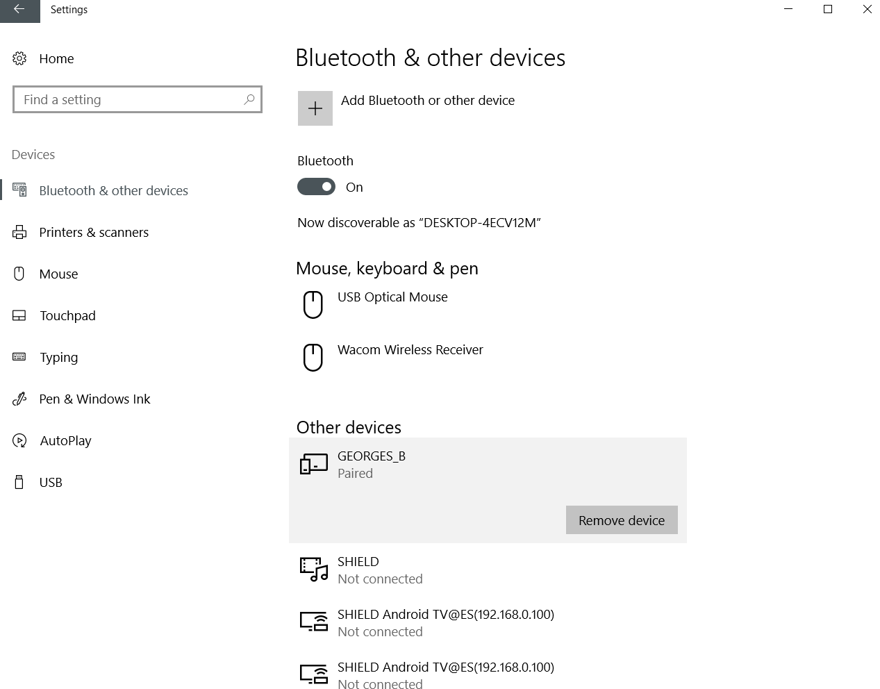
+ For changing the name of my Bluetooth module I typed ATNAMEGEORGES_B
+ For changing the baud rate I typed AT+BAUD6
And then after I was able to see the incoming data printed on my mobile screen I moved to writing the 2nd part of the code .
The 2nd part of the code tells the board to listen to the incoming data which will cause the led light to blink .
For making the code listening to the incoming data I used this code function ( BluetoothSerial.read() )
However, after I was done with writing the code and uploading it to the board I started writing the 2nd code using processing which will allow the computer to receive and send data so it can interact with my board.
The aim of this code is to let the computer receive 0 number from the output devices board and every time the value is equal to 0 it sends back number 1 to the board in order to make the led blinking.
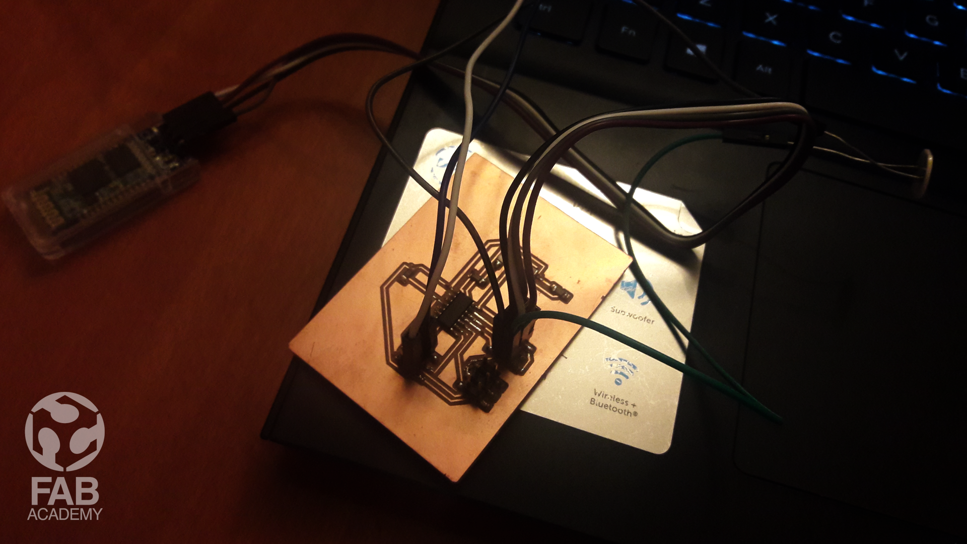
However, After I was done with the coding I connected my board to the Bluetooth module and once I was done I powered my board via FTDI cable I only used the VCC and GND pins as a result the Bluetooth led light started blinking based on incoming data from my laptop as shown in video #04
Below is Arduino code I used :
/* This code was modified by Georges Hanna Fab Academy 2018,NETWORKING AND COMMUNICATIONS The code was modified Based on the below codes : https://forum.arduino.cc/index.php?topic=386 https://maker.pro/arduino/tutorial/how-to-make-arduino-and-processing-ide-communicate */ #include//Include the software serial library in the sketch #define RxD 2 // Assign pin#2 on Attiny44 to be RX for receiving data ( This pin should be connected with the TX pin on Bluetooth module) #define TxD 1 // Assign pin#1 on Attiny44 to be TX for sending data( This pin should be connected with the TX pin on Bluetooth module) int LED = 7; // The led light is connected to Attiny44 pin # 7 SoftwareSerial BluetoothSerial(RxD, TxD); void setup() { BluetoothSerial.begin(9600); // Begin the bluetooth and set BaudRate to 9600 pinMode(LED,OUTPUT); pinMode(TxD, OUTPUT); // Telling Attiny44 to use TxD pin as an output pinMode(RxD, INPUT); // Telling Attiny44 to use RxD pin as an input } void loop() { BluetoothSerial.println(0); // Typing 0 every 6 seconds & this number will be sent to processing delay(6000); // Delay for 6 seconds char recvChar; // Define char datatype for reciving value from the blutooth device if(BluetoothSerial.available()){ //(If the connection is available recvChar = BluetoothSerial.read(); //Read the incoming data from processing if(recvChar == '1') // If the received data is 1 blink the led light { digitalWrite(LED,HIGH); // Turn on the led for half second delay (500); digitalWrite(LED,LOW); // Turn off the led for half second delay (500); } } }
Below is processing code I used :
    /*
  This code was modified by Georges Hanna Fab Academy 2018, INTERFACE AND APPLICATION PROGRAMMING.
  The code was modified Based on the below codes :
  https://abhikpal.github.io/blog/2013/10/05/getting-started-with-arduino-processing-serial-communication

  */


  import processing.serial.*; //Loading processing library
  char p = 0;
  char val=0;
  Serial myPort;   // Create object from Serial class
  void setup()
  {

  size(500,500);   // setting up the background size
  println(Serial.list());  //list all available ports
  myPort = new Serial(this, Serial.list()[2], 9600); //Checking the available ports and assigning baud rate  to match Arduino's sketch baud rate.
  }

  void draw(){
   while  ( myPort.available() > 0)
    {                           // If data is available,
    val = char(myPort.read()); // read the port value that is coming from Arduino and store it in val


     p=(val);
     println(p); //show the value of p and do the following
    if (p=='1'){   // if the value = 1

      background(255, 204, 0); //Change the background color to yellow
    }
    if (p=='0'){
      background(1);  //Change the background color

    }
      delay (1);
    }
    }
DOWNLOAD SECTION
+ NETWORKING_AND_COMMUNICATIONS.ino DOWNLOAD .
+ NETWORKING_AND_COMMUNICATIONS_PROCESSING.pde DOWNLOAD .